INTRODUCTION :
Make a sheet metal rolling machine :-
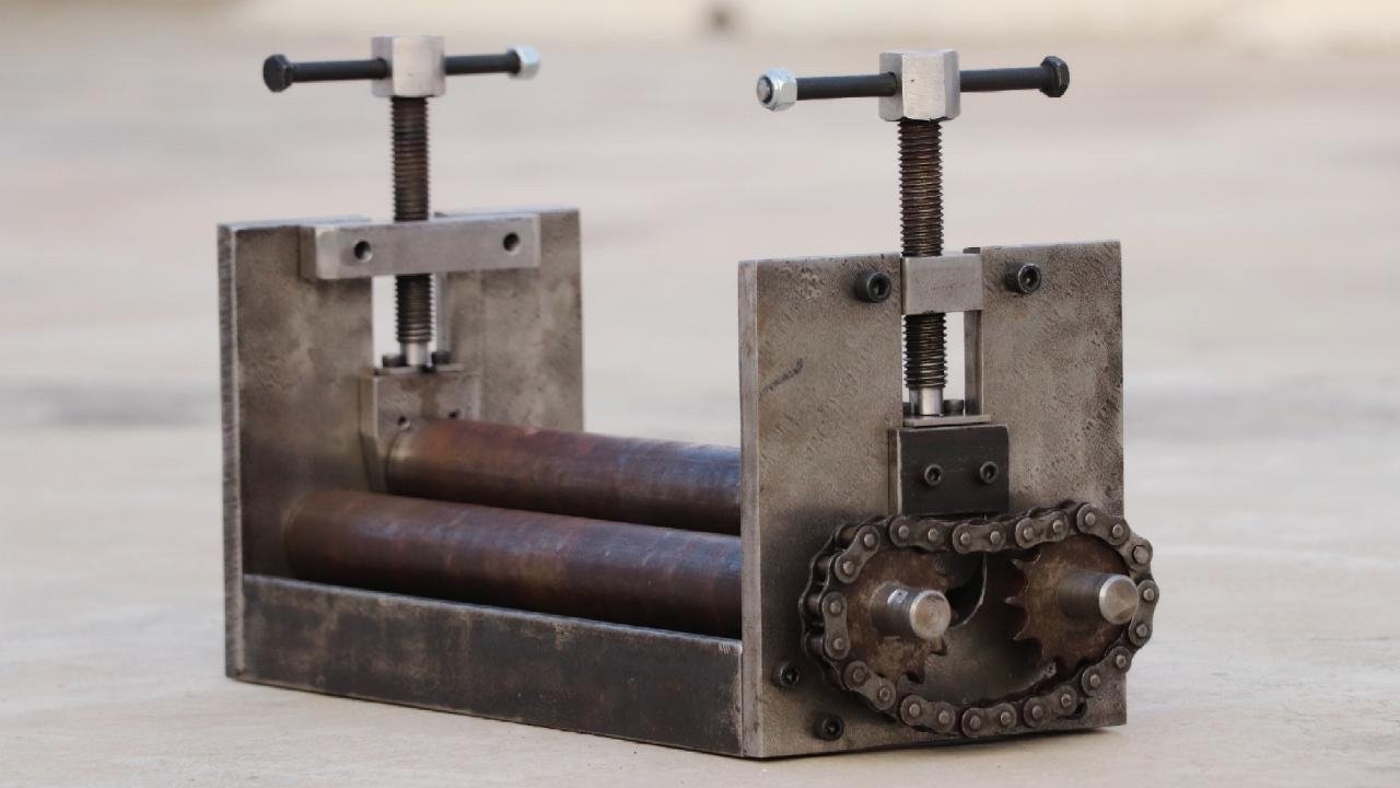
A sheet metal roller bender is a metalworking machine that allows the bending of sheet metal. This manually powered roller bender has three-shaft, used for bending of sheet metal and other metal parts in round shape. It is also known as a bending machine or roller bender or sheet metal bender machine.
Roller bender machine has also been called a rounder roller machine, which is universal forming equipment for rolling sheet metal plate into the cylinder, cone, curved and other shapes.
According to the principle of a three-point forming circle, the relative position change and rotational motion of the working roller make the metal sheet plate produce continuous plastic deformation to obtain the predetermined shape of the workpiece.
This type of manually or motor powered sheet metal roller bender is widely used in boiler, shipbuilding, chemical, metal structure, and machinery manufacturing industries.
The image shown, 3 roller bending machine usually takes two lower rollers as active roll and one upper roller can move vertically up and down.
Parts Used :
- 2 Nos. 1.5” L- section angle (13.25” length)
- 3 Nos. roller shaft 38mm diameter (two lower rollers has 16.5” length and one upper roller has 14” length)
- 4 Nos. bearings 6003 ZZ for lower roller
- 2 Nos. bearings 6002 ZZ for upper roller
- 2 Nos. Metal pieces 6.25”*6.75” for side support (10mm thickness)
- 2 Nos. chain sprockets and a chain
- 2 Nos. 5/8 bolts (5” length)
- 2 Nos. 5/16 half thread bolts with locknuts (5” length)
- 8 nos. ¼ allenky bolts (0.75” length)
- 4 Nos. 5/16 allenky bolts (0.75” length)
- 8 nos. 3/16 allenky bolts (0.75” length)
- 2 Nos. metal pieces 4”*1.25” (20mm thickness)
- Some other metal pieces
How to make :
Step 1 : cut the plywood sheet

The first step is to cut a 2 Nos. metal pieces 6.25”*6.75” for side support (10mm thickness). After cutting off the metal pieces, make a slot (32mm width) on both the metal pieces, as shown in the image.

Drill two holes of 35mm on both the metal pieces for 6003 ZZ bearing support.

I have used 3 Nos. roller shafts 38mm diameter (two lower roller has 16.5” length and one upper roller has 14” length). Turning the both end of the two lower rollers (same as the 6003 ZZ bearing bore), as shown in the image.


Assemble two lower roller shafts, metal pieces, chain sprocket, and chain-like image shows. The position of the chain sprocket is fixed by using allenky bolts.

Turing both ends of the upper roller for 6002 ZZ bearing. Make a bearing support parts for the upper roller by using metal pieces.

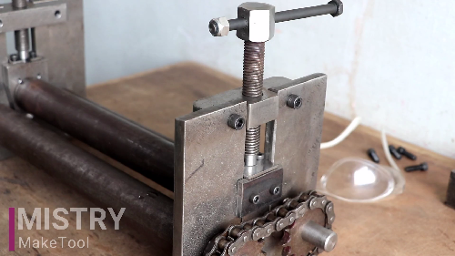
I have used 2 Nos. 5/8 bolts (5” length). Turning the end of both bolts and attached with the bearing support parts by using of allenky bolts, as shown in the image.

This upper roller bearing support parts is make up and down movement by using these bolts.

Attach 2 Nos. 1.5” L- section angle (13.25” length) with this assembly to make a base part.
And in the last, attach the handle with the drive sprocket.

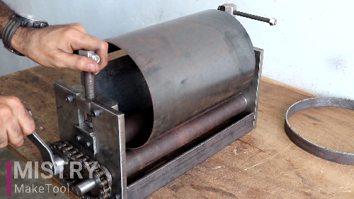
During the operation, one end of the metal plate is feed into three roller plate between the upper and lower roller, and then upper roller brings downward displacement on the metal plate, which make the plate under it generate a certain plastic bending deformation due to compression.
