INTRODUCTION :
DIY Metal Bender for Round Shapes
Want to create perfect curves in metal pipes and pieces? Building your own metal bender can be a rewarding project, saving you money and allowing for custom creations. This guide outlines the construction of a bender using readily available metal parts, an angle iron frame, metal C-channel base, and a 3-ton hydraulic jack.
Metalworking involves inherent risks. Always wear appropriate safety gear, including eye protection and gloves, and exercise caution when working with heavy materials and tools. This project is for experienced DIYers; if you’re unsure about any step, consult a professional.
This project requires a good understanding of metalworking techniques and the use of power tools. If you are not comfortable with any of the steps, seek assistance from someone with experience. Research different bending die designs and consider the specific requirements of your project. Online forums and metalworking communities can be valuable resources for information and advice.
Materials :
- Metal C Channel:
2 Nos. 3” wide C-channel and 16” length (For base)
- Metal L Angle: For the main frame uprights. Choose a substantial size based on the bending force.
2 Nos. 2” L-angle and 10” length (For column support on base)
4 Nos. 1.5” L-angle and 8” length (For bearing support pillar)
2 Nos. 2” L-angle and 8” length (For bearing support base)
2 Nos. 2” L-angle and 9” length (movable bearing support base)
- Metal Plate: For reinforcing the jack mounting point and creating brackets and column.
2 Nos. 3”*4” and 6mm thickness for base
4 Nos. 4”*16.5” for main column
- Bearings: These will support the bending shaft.
4 Nos. UCP206 bearings
2 Nos. FL206 bearings
- Shafting: A hardened steel shaft for the bending roller.
2 Nos. 30mm diameter shafts with 50mm diameter collar and 8” total length
30mm diameter shaft and 11.5” total length
12mm diameter shaft and 18” length (For handle)
16mm diameter shaft and 4.5” length
- Hydraulic Jack 3-ton): Provides the bending force.
- Bolts, Nuts, Washers: For assembly.
- Welding Equipment (Optional): For joining metal parts. Bolting is a good alternative.
- Measuring Tools: Tape measure, square, marker.
- Drilling Equipment: Drill and drill bits.
- Metal Cutting Tools: Angle grinder, hacksaw, metal cutting saw.
- Safety Gear: Safety glasses, gloves.
How to make :
- Base Construction:
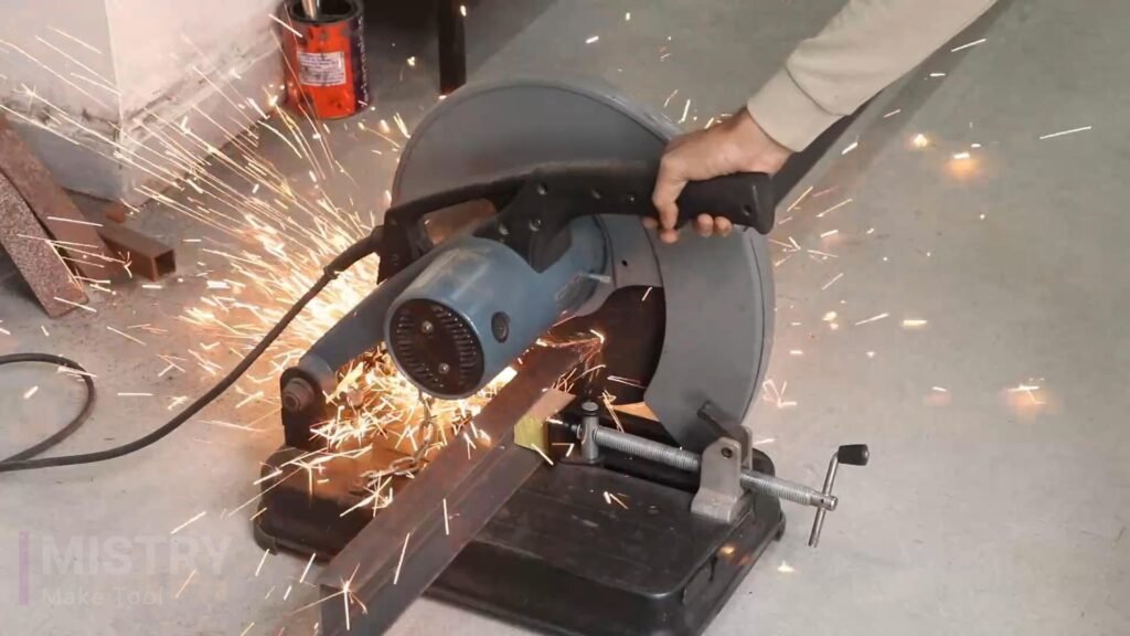
Cut the C-channel to the desired length. I have used 2 Nos. 3” wide C-channel and 16” length to make base of the metal bender.
Weld or bolt a flat metal plate across the open side for added strength and stability. This plate also serves as a mounting point for the jack and frame uprights.
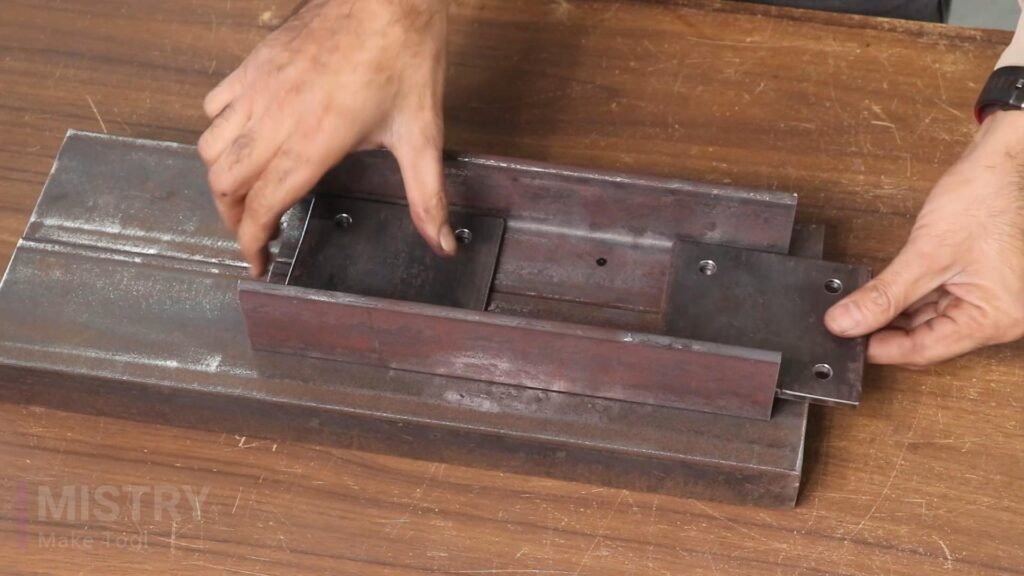
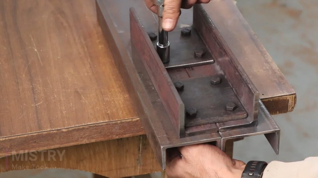
2. Frame Assembly:
Cut the L-angle into two equal lengths for the base. Weld or bolt these uprights to the C-channel base, ensuring they are perfectly jointed. Reinforce the joints with gussets or additional angle iron pieces.
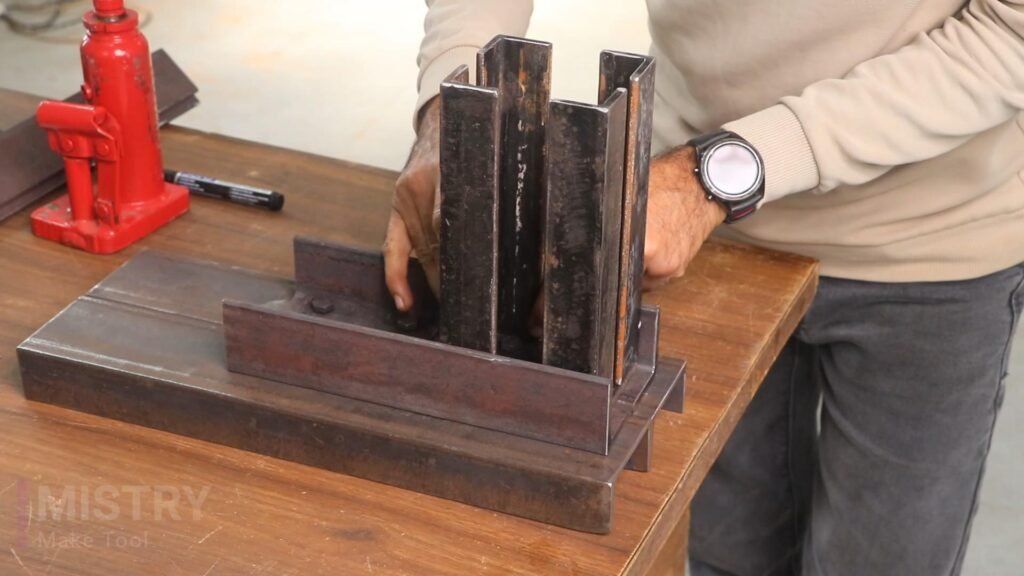
Attach 4 Nos. 1.5” L-angle and 8” length on the base for bearing support uprights. Make sure they are perfectly vertical.
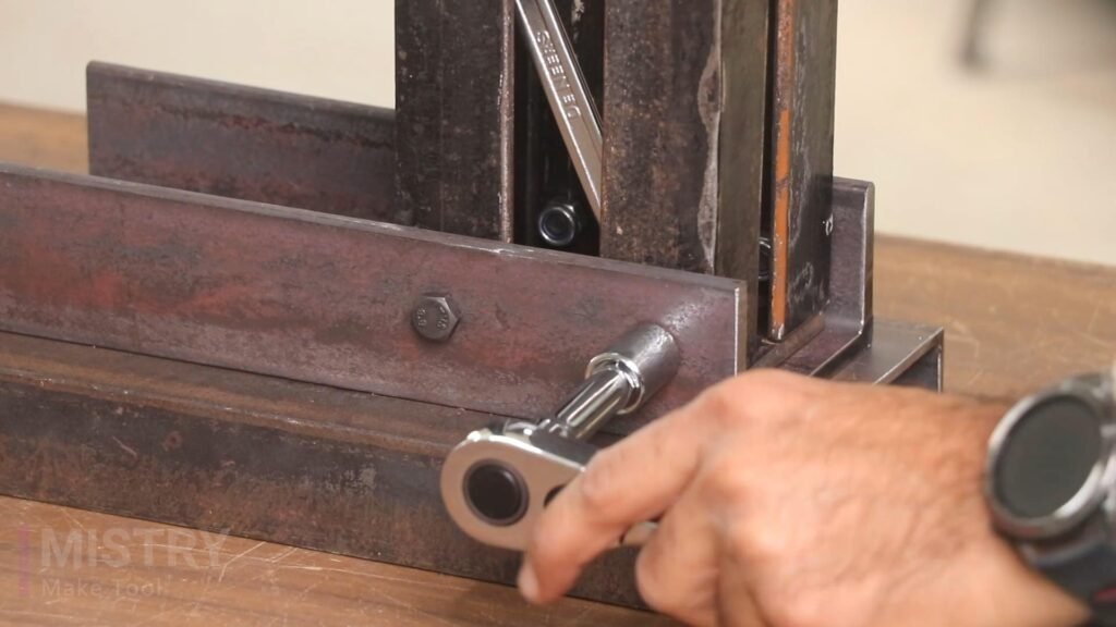
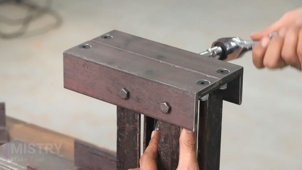
Next step is to make the bearing support part. I have used 2 Nos. 2” L-angle and 8” length for bearing support base. Attach this part on the uprights using of nut and bolts.
3. Main Column Plates And Movable Base:
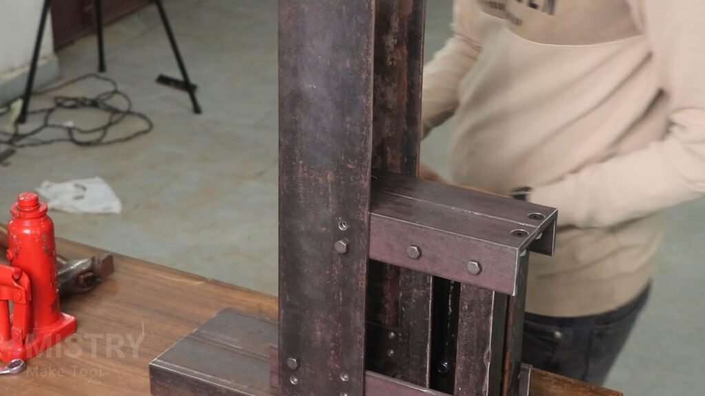
Next step is to attach the main column plates with this frame structure. First i used only two plates for column for two sides of the frame. but when i start to bend the workpiece using hydraulic jack it pushes the plates and it bend from the end so i decided to increase its strength and i used two more plates and total four metal plates of 4”*16.5”are used for main column part.
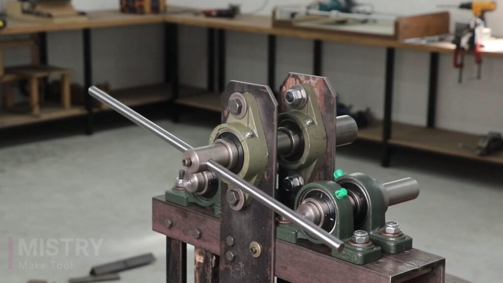
In this image it shows only two plates but after that i change it and add another two plates.
Drill holes on plates and attach these plates on both sides of the frame using nuts and bolts.
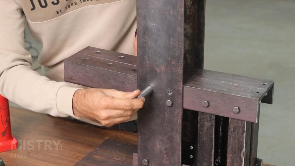
Next step is to make movable (Up-down) bearing support base. I have used 2 Nos. 2” L-angle and 9” length to make this base. Mount the base from one end with the column plates using 4.5” long 16 mm diameter shaft, so the other end is move up and down by using hydraulic jack.
4. Bearing Mounts:
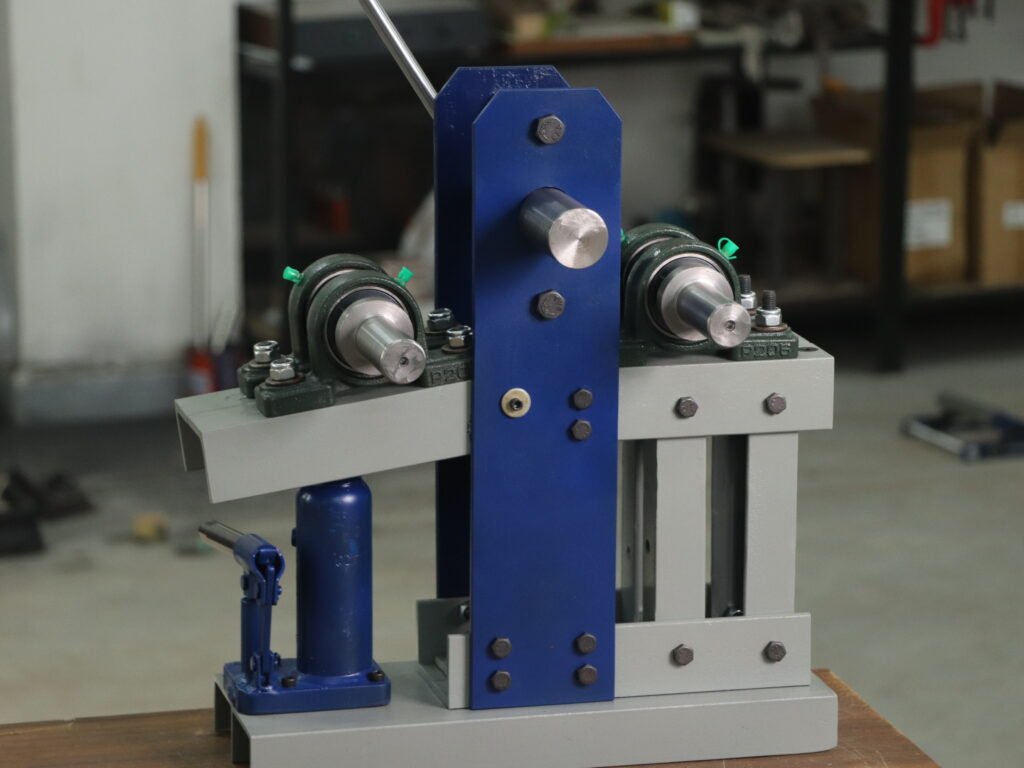
In this bender machine I have used 4 Nos. UCP206 bearings and 2 Nos. FL206 bearings. Create mounting points for the UCP206 bearings. Ensure the holes are aligned so the shaft will run smoothly. 2 Nos. UCP206 bearings are mounted on fixed base and other two are mounted on movable base.
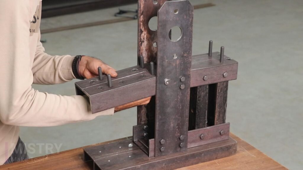
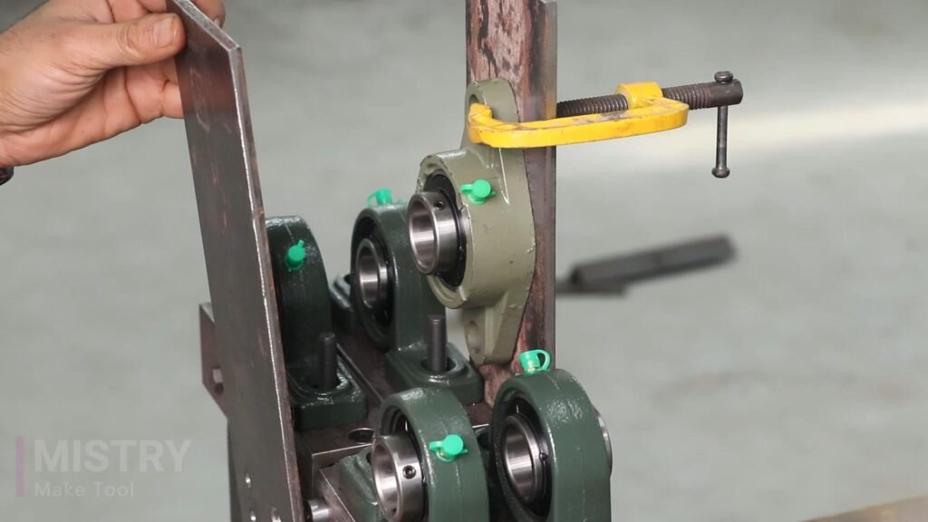
On main uprights, near the top, create mounting points for the flanged bearings (FL206). Accurately drill holes for the bearing bolts. Weld or bolt the bearings to the uprights.
5. Hydraulic Jack Mount:
Weld or bolt a sturdy flat 6mm metal plate of 3”*4” size to the C-channel base. This is the jack’s mounting point. Position the jack so its ram pushes upward against the workpiece.
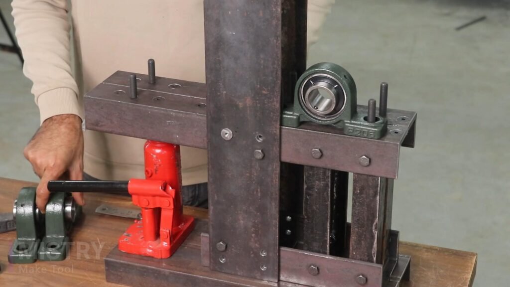
A common approach is to have the jack push against a movable base to forcing it against the bending shaft and workpiece.
6. Shaft assembly:
Insert the shafts through the bearings mounted on the uprights. The 30mm diameter shafts with 50mm diameter collar and 8” total length are mounted on both bearing support base.
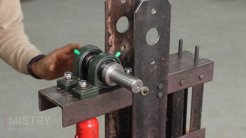
Another shaft of 30mm diameter and 11.5” total length is mounted on main column plates, as shown in the image.
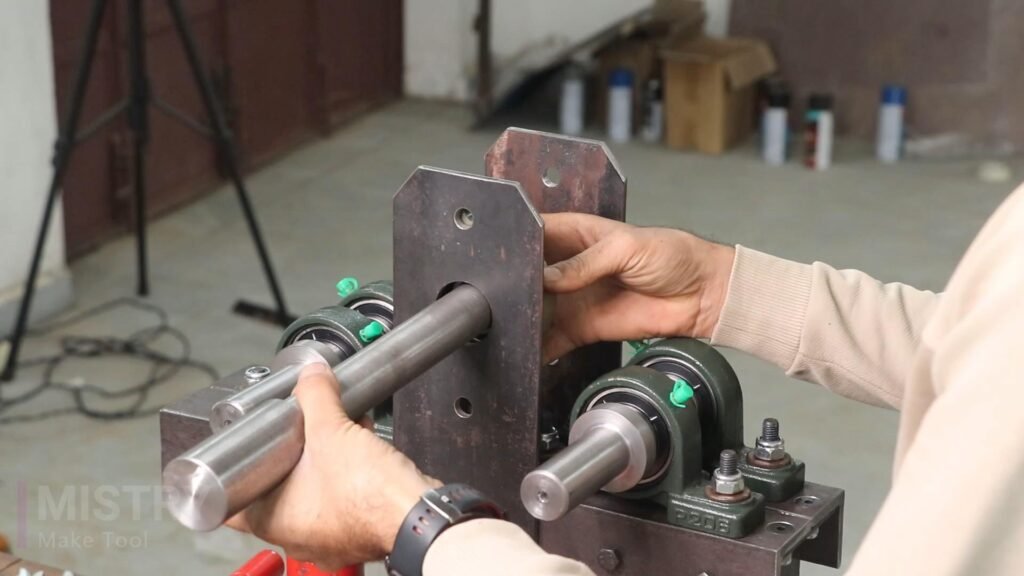
Attach the handle of 12mm diameter shaft and 18” length. This shaft is insert in the main column shaft.
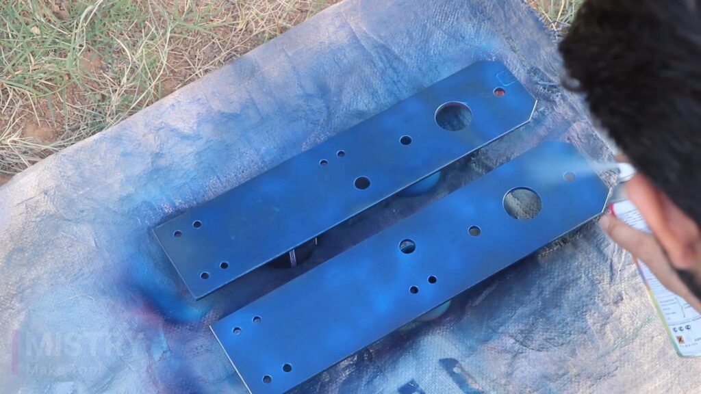
Paint this bender machine to protect it from corrosion and for better look.
7. Testing:
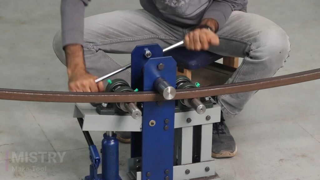
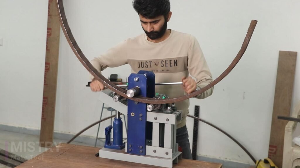
Ensuring everything is securely fastened. Test the bender with a scrap piece of metal pipe. Apply pressure with the hydraulic jack, gradually bending the pipe to the desired shape. Make any necessary adjustments to the supports or bending shafts to achieve a smooth and consistent bend.
Additional Information and Description:
- Bearing Selection: FL206 flanged bearings are recommended for easier mounting. Ensure they are rated for the load and shaft diameter. UPC 206 are pillow block bearings, which require a different mounting method.
- Shaft Material: Use hardened steel for the shaft to resist bending and wear.
- Workpiece Material and Thickness: The material and thickness of the workpiece affect the force required for bending. Thicker and harder materials require more force.
- Safety: Always wear safety glasses and gloves. Ensure all components are securely fastened. Use a hydraulic jack with a pressure relief valve to prevent overloading.
- This refined design, incorporating bearings and a robust frame, will provide a smoother and more controlled bending experience. Remember to adapt the dimensions and materials to your specific needs and the size of the workpieces you intend to bend. If welding, ensure you have the proper equipment and skills. Bolting is a strong and viable alternative.

