INTRODUCTION :
Woodworking lathe machines are the oldest variety of the woodworking workshop. An adjustable horizontal metal rail – the tool rest – between the material and the worker accommodates the positioning of the shaping tools or chisel, which are usually hand-held. After shaping operation, it is common practice to press and slide sandpaper against the spinning object to smooth the surface of the work piece with the metal shaping tools. The tool rest is usually removed during sanding operation, because it may be unsafe to have the workers hands between it and the spinning wooden work piece.
Many of the woodworking lathe machines can also be used for making bowls, plates and handles of the hammer and chisel and also some decorative items. The bowl needs only to be held at the bottom by one side of the lathe machine. The work piece usually attached to a metal face plate attached to the spindle shaft. With many lathe machines, this operation happens on the left side of the headstock, where are no rails and therefore more available clearance. In the woodworking lathe machine a specific curved tool rest may be used to support tools while shaping the inside.
The main purpose of the woodworking lathe is woodturning. Woodturning is the craft of using the woodworking lathe with hand-held tools or chisel to cut a shape that is symmetrical around the axis of rotation. The lathe machine operator is known as a turner, and the skills needed to use the tools were traditionally known as turnery.
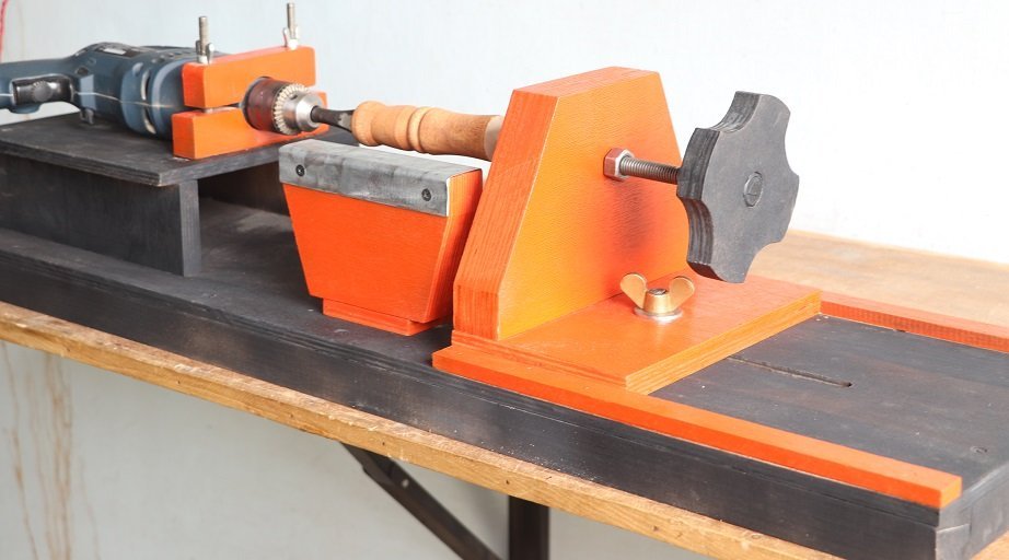
Here I make a drill powered woodworking lathe for my own use.
Parts Used :
- For base part
- 12mm Plywood sheet (35”*11”)
- 1.25”*1.50”*35” Wooden blocks (2 Nos.)
- 1.25”*1.50”*8” Wooden blocks (2 Nos.)
- Screws
- For drill support
- Drill machine
- 12mm plywood (8.5”*10”)
- 12mm plywood (3.5”*10”) 2 Nos.
- Wooden blocks ¾” thickness (5” length)
- 2 Nos. 5/16” Bolts (4” length) with fly nuts and washers
- Movable part / Tailstock part
- 2 Nos. 1” Wooden strips (14” length)
- 3 Nos. 19mm plywood pieces (9”*5”)
- ½” Bolt (8” length) with nut
- ½” bolt (2” length) with fly nut and washer
- Tool support / Tool rest part
- 3 Nos. Plywood pieces
- 3/8” Bolt (2” length) with fly nut and washer
- 22 Gauge metal sheet (6”*4”)
- Chisel
How to make :
Step 1 :- Cutting of plywood parts

The first step is cutting of plywood parts of its proper dimension. I have used 12mm and 19mm plywood sheet to make this lathe. For the base part I have used 12mm plywood sheet. Also cut the wooden blocks (1.25”*1.50”) of a 35” length and 8” length and other plywood parts as shown in the parts used section.
Step 2 :- Make a base

After cutting of plywood parts and other components, next step is assembly of parts. So first of all make a ½” slot of 10” length on plywood part of a base. Then after assemble the plywood base and wooden blocks by using of screws. Now, the base of lathe is ready.
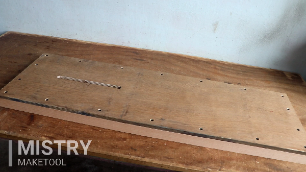
Step 3 :- Make a support for drill / Headstock part

Third step is, make a support for drill machine. I have used 13 mm capacity drill machine. You can show the parts used to make a support of drill in the section “parts used” for drill support. So, next step is assembly of plywood parts by using of screws. And also attach the wooden block with round hole on it, to attach the drill on fixed position of drill support part as shown in the image.

Step 4 :- Make a movable part / Tailstock part

After attachment of drill on its fixed position, Forth step is make a movable part. You can show the dimension of the parts on “movable part” section of parts used. First of all attach the wooden strips to guide the movable part of the lathe by using of nails. Also assemble all the parts of “tailstock part” as shown in the image. Attach the movable part by using of the ½” bolt of 2” length on the right side of the base through the already provided slot.

Next step is attachments of the ½” bolt of 8” length with nut and its handle as shown in the image. The handle is used so you can easily spin the bolt in and out. You can easily hold the work piece by using of this bolt.

Step 5 :- Tool support / Tool rest part
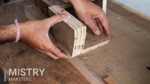
Fifth and last step is make a tool support or tool rest part. All the parts and its dimensions are shown in the “Tool support” section of the parts used. Assemble all the parts as shown in the image.
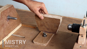
Attach this part on the base by using of bolt and fly nut through the already provided slot. You can adjust the depth by moving the tool rest part in and out by using of the fly nut and bolt.

Also i attach the 22 gauge tin on the tool rest part for better performance. After that i painted it.

Now, the woodworking lathe is ready to use. I have used chisel for turning operation on the work piece.


