INTRODUCTION :
How To Make an Oscillating Sander Machine
Introduction:-
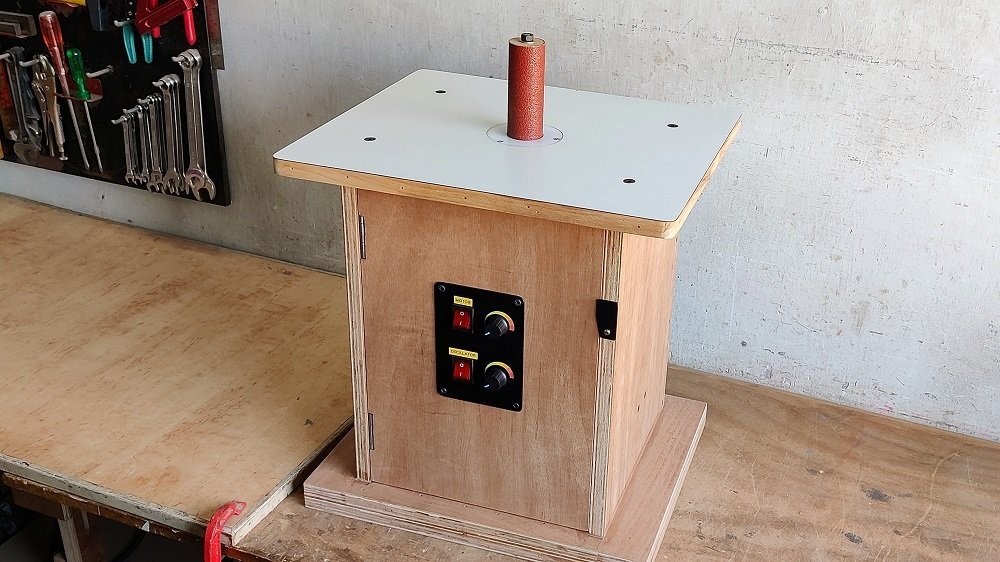
A sander is a power tool used to smooth surfaces by abrasion process with sanding paper. Sanders has the means to attach the sanding paper and a mechanism to move it rapidly contained within a housing of the machine. Woodworking sanders are usually electrically powered, and those used in auto-body repair work by compressed air. There are many different types of sanders for different purposes. In this post, I show you how to make an oscillating sander.
An oscillating spindle sander is a sander mounted on a spindle that both rotates and oscillates up and down along the axis of the spindle. This type of oscillating sander is good for sanding curves and contours that would be difficult with hand or orbital sanding. The spindle sander is normally used for sanding inside corners. There are various spindles that range from 20mm to 65mm. The spindle also oscillates up and down as it rotates to produce a smooth finish. The machine has an on/off power switch located on the control panel. Make sure the material you are cutting is free of all foreign objects. In this machine, I attached two-speed controllers. One controls the spindle speed and the second controls the up-and-down movement.
An oscillating spindle sander machine sands the edges of contoured or irregularly shaped workpieces. The wooden sanding table provides a solid platform for supporting workpieces. Sanding drum sleeves are easily replaceable and available in a variety of sizes and grits.
Parts Used :
2Nos. plywood 17inch * 14inch (19mm thickness) for base
4Nos. plywood 16inch * 12inch (19mm thickness) for side walls
4Nos. plywood 8.5inch * 6.5inch (19mm thickness) motor support
2Nos. plywood 8inch * 6.5inch (19mm thickness) motor support
Plywood 8.5inch * 8inch (19mm thickness) motor support
24v dc electric motor 2650rpm
12v Wiper motor
AC to DC converter
2Nos. speed controllers
2Nos. switches
5mm metal piece 7inch length (connecting rod)
10mm metal piece 2.5inch length (connecting rod)
1.25-inch L-section angle (4inch)
Sheet metal piece 6inch * 4inch
8mm smooth rod 6inch length (spindle)
16mm hollow shaft with 8mm hole (for spindle joint)
8mm flange bearing (for spindle support)
2Nos. 12 mm smooth rods (12inch length)
4Nos. 12mm linear bearings (SC12UU)
4Nos. 12mm smooth rod supports (shaft support)
16mm compression springs
Drum sander
PVC rings
Electric wires
2Nos. 2inch hinges
Bolts and nuts, Allen key bolts, screws, guff screws, nail
How to make :
The first step to make this oscillating spindle sander is – to cut the accurate size of plywood pieces as per the dimensions shown in the parts used section of this post.
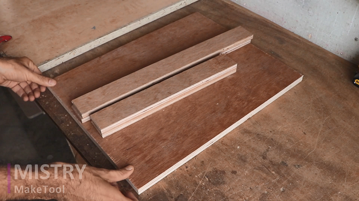
As per the dimensions, attach all the plywood pieces to make the structure of the spindle sander. For the base part, I have used 17inch * 14inch (19mm thickness) plywood and for side walls, I have used 4Nos. 16inch * 12inch (19mm thickness) plywood pieces.
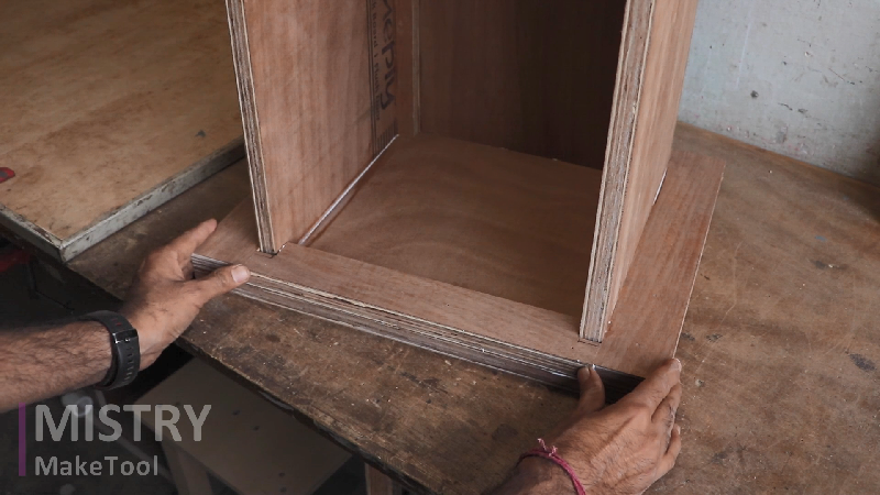
The next step is to make motor support. I have used a 24v dc electric motor to make this spindle sander. To make the motor support structure I have used 8.5inch * 6.5inch, 8inch * 6.5inch, and 8.5inch * 8inch plywood pieces. For better strength of the structure, I have used a double layer of plywood pieces.
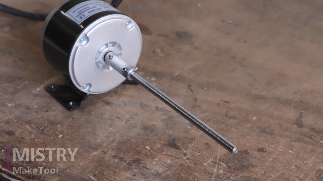
Attach the electric motor inside the motor support structure by using bolts and nuts.
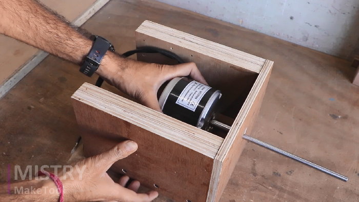
To make the oscillating spindle mechanism I have used 2 nos. 12mm smooth rods, 4nos. 12mm linear bearings, and 4nos. 12mm smooth rod support.
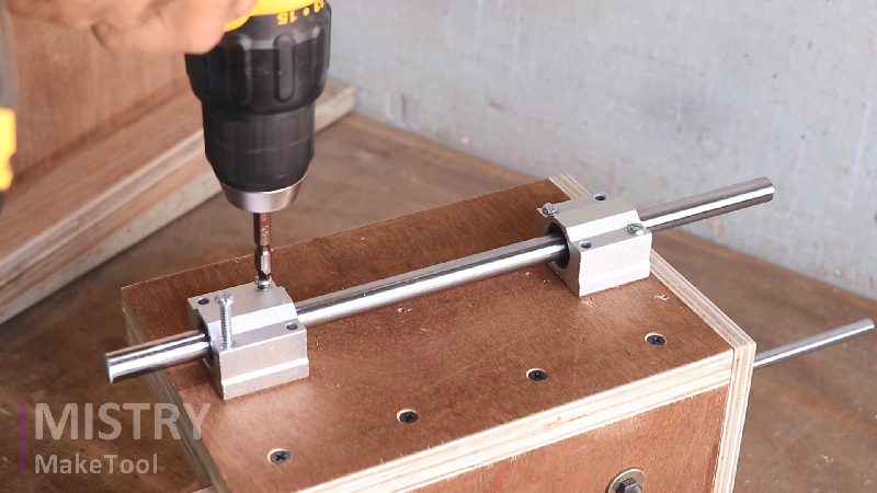
Attach these 12mm linear bearings on two sides of the motor support structure by using screws, as shown in the image.
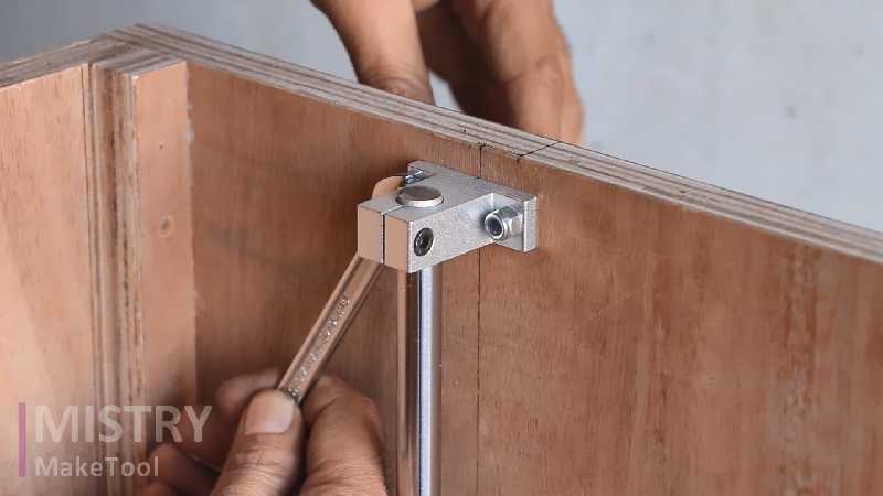
And attach the 12mm shaft support on the two sides of the main structure, as shown in the image.
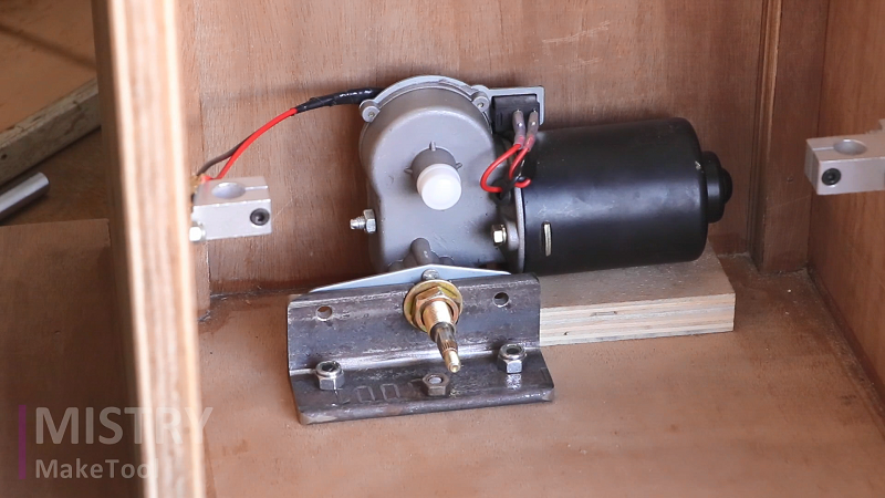
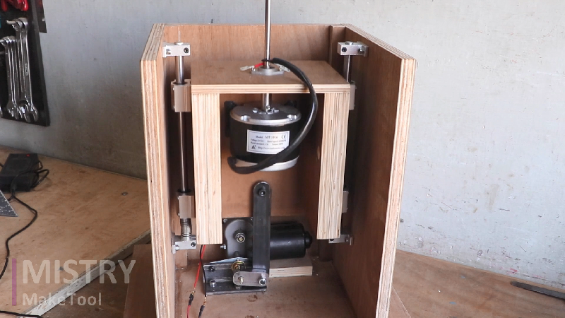
The next step is to attach the wiper motor. The wiper motor is used to provide the up and down movement to the electric motor. The wiper motor is attached to the main structure with the help of the 1.25-inch L-section angle (4-inch length), as shown in the image.
Attach the motor support structure in the main structure with the help of smooth rods and shaft support. Shaft support is fixing the position of the smooth rod and linear bearings are providing the up-and-down movement to the electric motor.
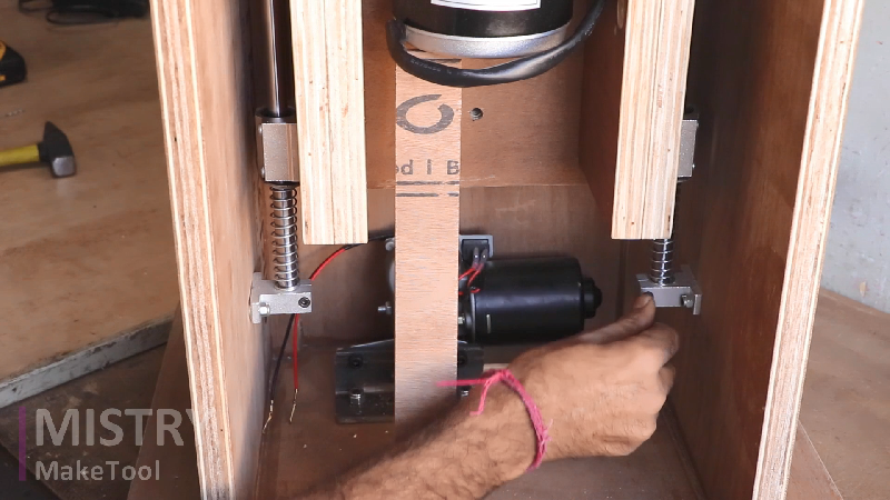
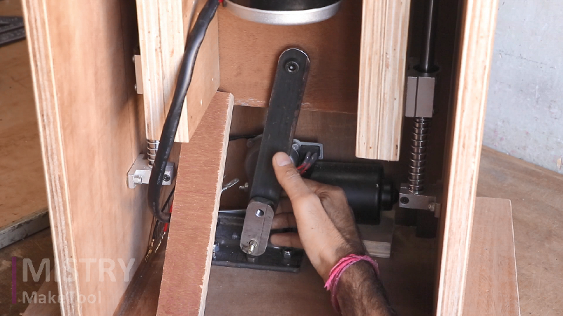
The next step is to make connecting rod mechanism. Connecting rods are connecting the electric motor structure to the wiper motor. I have used a 5mm metal piece 7inch length and a 10mm metal piece 2.5inch length as connecting rods, as shown in the image.
The next step is to attach the AC to the DC converter.
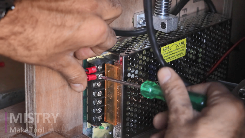
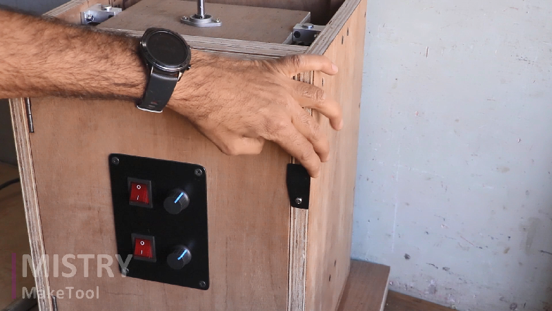
Also, attach the two switches and two-speed controllers. One is for the wiper motor to control the oscillating movement and the second is for the electric motor to control the speed of the spindle sander.
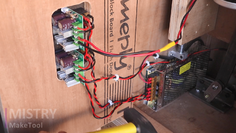
The switches and speed controllers are attached to the front side of the machine. The front wall is not fixed, it is foldable. Front side plywood is attached by 2Nos. 2-inch hinges so it can be easily opened and closed.
The next step is to make the workpieces support part. To make it I have used 17inch * a 14inch plywood piece. I have drilled a 65mm hole in the plywood by using a 65mm hole saw. So up to 65mm drum sander can be installed in this spindle sander.
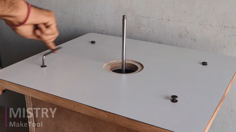
I have also used PVC rings to fill the gap between the drum sander and workpiece support plywood hole.
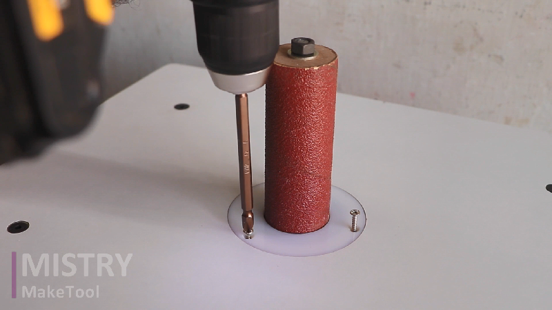
And at the last attach the drum sander.
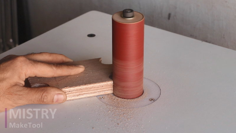
The spindle sander is normally used for sanding inside corners. It can install various spindles ranging from 20mm to 65mm. I can easily change the drum sander if I need to change it.
For security reason, the machine has an on/off power switch located on the front side of the machine.
Make sure the material you are cutting is free of all foreign objects. Do not sand materials that may have nails or screws as they will damage the drum and may cause injury to you.





i enjoyed your videos and will use these instruction to build the tools